mmsmse
2007
modular open source hardware research project
The modular core of each device on a Lazymode network is the Modified Miller Montréal-Saskatoon Miller Engine (MMSMSE) circuit, released as an open source hardware project in December 2008. The following is a text from an aritcle published in Vague Terrain 12: Device Art, curated by Rob Cruickshank. It accompanied the public alpha release of the MMSMSE as open source hardware.
NB: The MMSMSE was formerly abbreviated as MMMSE and the Lazymode project former working title was Relaxation Oscillator Network. Retained below as in the original article text.
MODIFIED MONTREAL-SASKATOON MILLER SOLAR ENGINE
Alpha 0.1.1
Peter Flemming
December 2008
Contents:
- Introduction
- Disclaimer
- What is an MMMSE?
- What does the name mean?
- A Bit Of Technical Background: What is a Relaxation Oscillator?
- Artworks Using The MMMSE
- Brief Technical Description
- My Modifications
- MMMSE In Operation
- How To Make Your Own
- Making Your Own Modifications
- Parts List
- Known Errors, Needs Work
- Sinks and Sources
- Links
Introduction
In this article I present an electronic circuit called the Modified Montréal-Saskatoon Miller Solar Engine (hereafter abbreviated MMMSE). This is released as alpha-stage open hardware for use in art projects. The most recent information on this project will live here.
This article attempts to:
- briefly provide some background and context of the MMMSE
- show how I have used the MMMSE in my own work
- make available all necessary files for creating or modifying your own MMMSE
- function as a sort of how-to for making and using the MMMSE
Disclaimer
Hopefully there is something of interest here to a broad audience. However, this article contains a fair amount of technical info geared to folks who have an interest in electronics. Therefore, I've divided this article in two. The first part is more general, followed by the technical bits, which can be skipped if that isn't your thing.
What is an MMMSE?
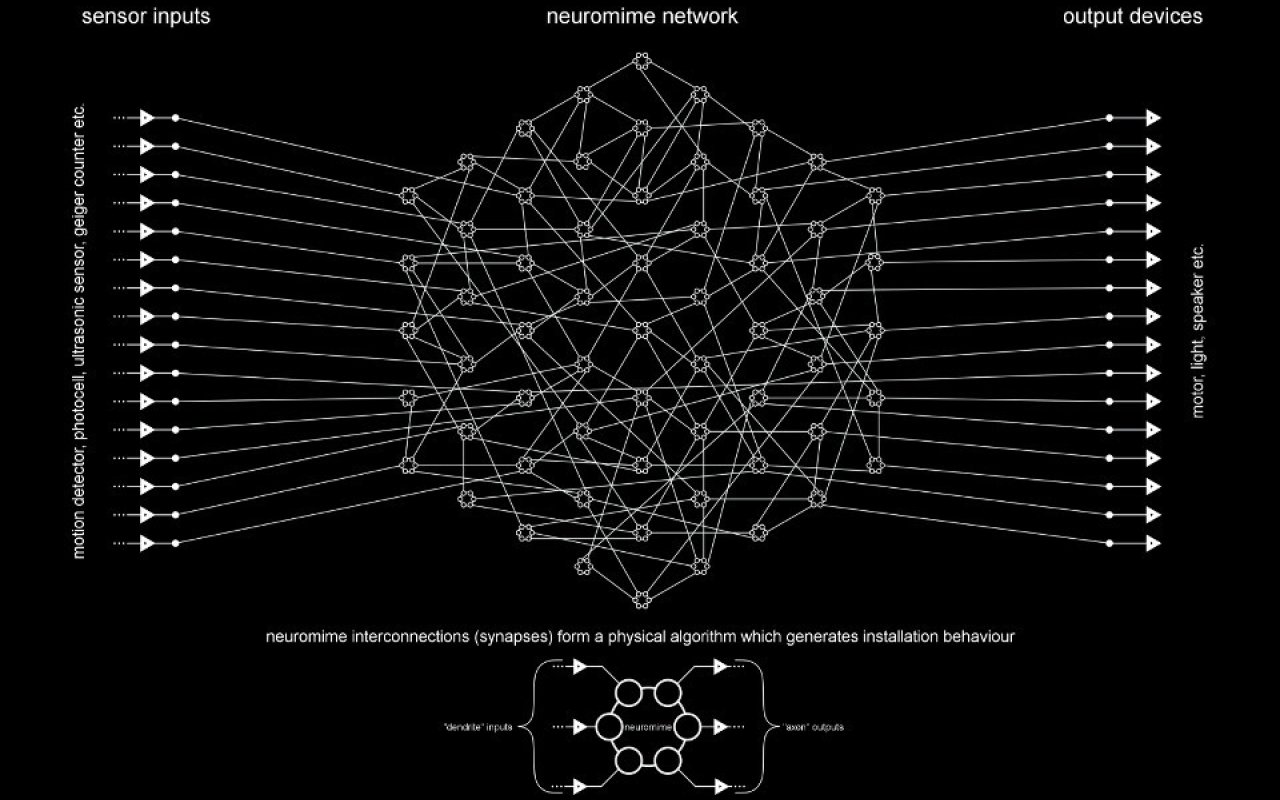
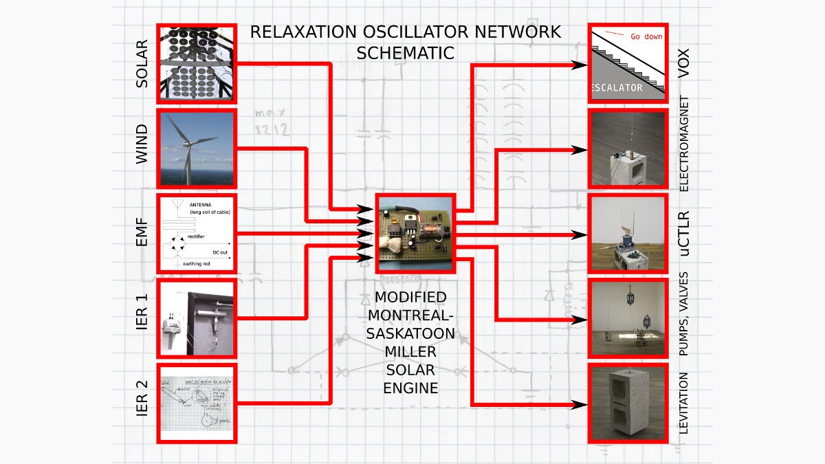
An MMMSE is a small, simple circuit that is the common, modular core component of a larger project I am working on tentatively called Relaxation Oscillator Network (hereafter abbreviated RON). RON is a system of independently operating electrical devices that use no batteries or AC. Instead, they harvest power from light, wind, electromagnetic fields and other sources. Machines in the network are in Lazymode: there are long periods where they appear to be doing nothing, yet are resting, eating energy, waiting for the right moment, until they accumulate enough to act. Two examples of Lazymode machines are described below, and videos accompany this text.
Currently the heart, brains and stomach of each device in the RON is an MMMSE. In the MMMSE a super capacitor is slowly charged by available sunlight through a solar panel (or other source). I didn't invent this idea (see here for the Miller solar engine). However the MMMSE is my own modification, optimized for maximum slack.
Among other things, this project is an exploration of:
- mechanics as a metaphor for collective or individual desires
- the possibility of critiquing technology by relatively low or obsolete-tech means
- the use of alternative power sources in media artworks
The use of the word "network" is perhaps a bit of a misnomer: there is no communication in the traditional manner with electric signals, and many of the Lazymode machines appear singular and self-contained. However, in another sense, they are physically, intrinsically linked by the fundamental protocol of available energy.
What does the name mean?
The name is a parody of certain automotive engine naming conventions where the city in which the engine is produced becomes part of it's nomenclature. I started work on this project in a residency in Saskatoon and refined it a lot in my studio in Montréal.
A Bit Of Technical Background: What is a Relaxation Oscillator?
Relaxation oscillator is a technical term for a type of timer circuit based on the charging and discharging of a capacitor. Imagining electricity as drops of water: a capacitor acts like a bucket that can be filled and drained, over and over. This can be a basis for a clock signal, albeit very "relaxed" and imprecise, by gigahertz standards.
I really like the connotations of this term removed from a technical context. It implies the idea of a machine that possesses the capacity for relaxation.
Artworks Using The MMMSE
Videos of two works using the MMMSE accompany this text.
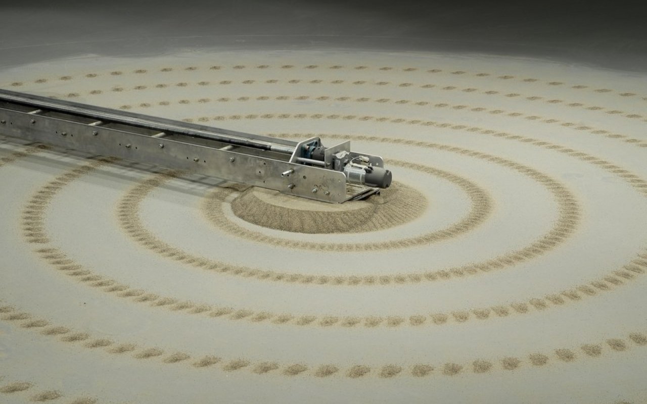
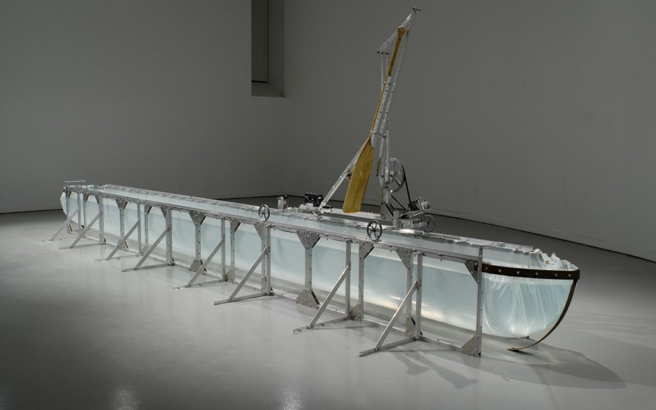
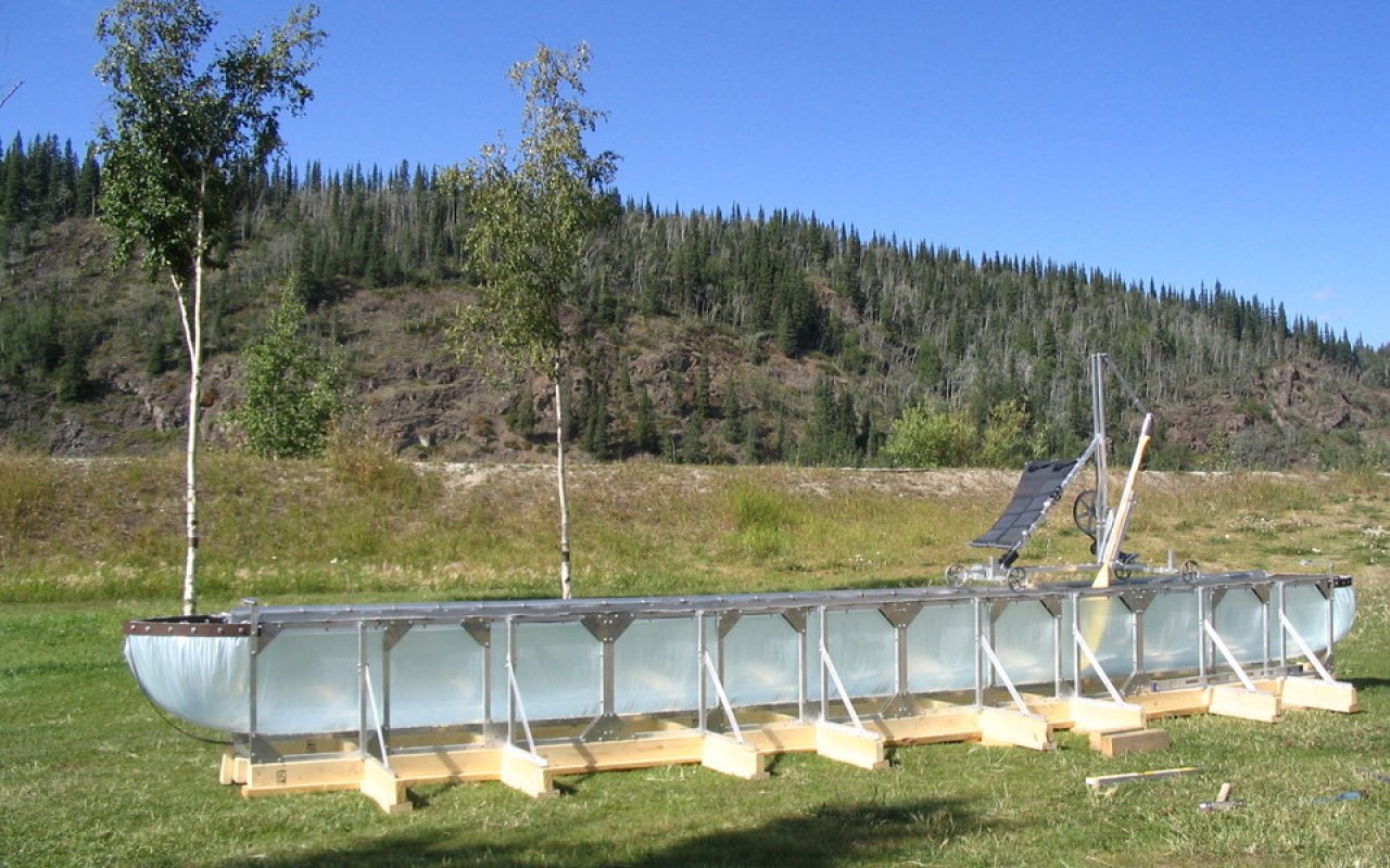
Canoe [Solar Power Version]
This was the first use of an early version of the MMMSE in Dawson City, Yukon
A 25 foot long trough of water, resembling a boat, provides a means for a gunwales tracking mechanism to slowly, endlessly paddle to and fro. Canoe was first constructed in 2001 in a studio beside Halifax harbour. It draws visual inspiration from the bridges and water vessels of this port. Conceptually, it grew from an interest in technological obsolescence: how things (like canoes) make shifts from utility to leisure.
In the original indoor version Canoe runs on rechargeable batteries, with a continuous, smooth motion. In Dawson, it was placed outdoors, alongside the Yukon river, showing up in an absurd way the paleness of its artificial river. The source of power was sunlight, feeding an MMMSE. Motion was intermittent, dependent on the intensity of sunlight. It ranged from near standstill in overcast conditions to perhaps 1 or 2 strokes every minute in full light.
Canoe is a rigid, rules-based system of repetitive mechanics, preset circuitry and angular construction. I wanted to place this type of system somewhere where it would be effected and affected by factors that are not predictable: elements, sunlight, the responses of passerby etc. Dawson was the ideal place for this experiment.
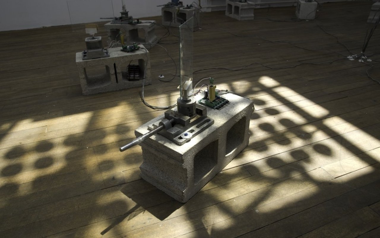
This is recent work from Spring 2008 using the current version of the MMMSE
12 stepper motors rotate panes of glass. The vibrations of the motor resonate in the glass, which acts as a mechanical amplifier, producing a ringing tone. The pitch of varies with motor speed and can be precisely controlled.
Skylight mounted solar panels feed power to the motors and an MMMSE. The motors sing according to available light. At rest, the silent motors eat light and store energy. Upon full charge, they commence singing. As the stored voltage dies, pitch and volume slowly drop. After several minutes they must stop and rest again.
When starting to sing, the motors gradually glissando up to the particular home note to which they are tuned. Each motor's note is part of a major chord. Because the motors are independent, working according to relaxed parameters, they start and stop at different times. While not random, the overall effect is difficult to predict and varies with sunlight, cloud patterns, time of day and so forth. Richly resonant in changing dissonances and harmonics, a complex drone that never repeats itself is created.
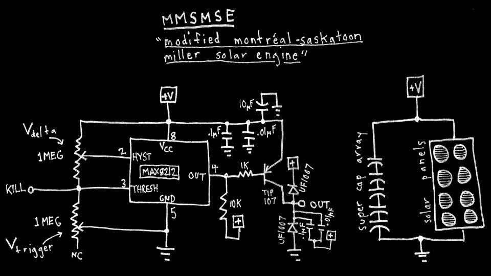
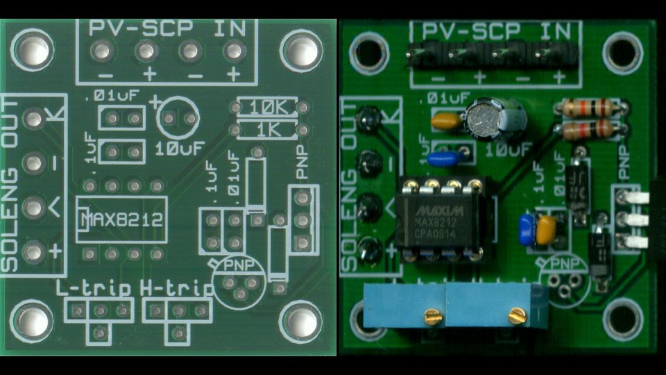
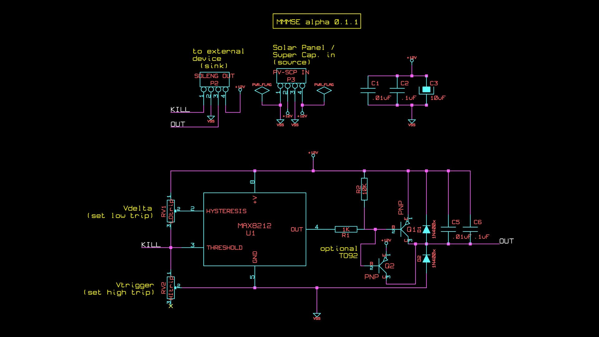
In this section I'll refer to pictures of a finished board and a schematic. Accompanying this article is an archive file (mmmse_alpha-0.1.1_all), conveniently provided as .zip and tarball, as you prefer. See the left-hand side to download. You can also download just the pcb fabrication files, if you wish.
The archive file mmmse_alpha-0.1.1_all contains:
- a read_me file describing full contents in detail
- all files needed to modify or have manufactured MMMSE boards of your own
- a schematic in .png format
- custom component and footprint libraries for Kicad PCB design software
- relevant datasheets
- tuning tips documentation
- other stuff
Brief Technical Description
This circuit is based on the MAX8212 voltage supervisor integrated circuit. It is meant for "supervising" the power supply for, say, a computer and give a warning if the voltage is too high or too low. This behaviour can be adopted for use as a solar engine. I learned about this from the manual for a Solarbotics kit and the MAX8212 datasheet (pdfs are in the tarball).
Basically, the chip watches its supply voltage. When the voltage reaches an externally set upper trip point, an output pin goes active low. When the voltage falls below an externally set lower trip point, the output goes open. It does this via an external resistor network (2 trim pots) interacting with a precise internally generated 1.15 volt reference. You can hook-up the active low output to a PNP transistor and drive a motor or something.
My Modifications
I found a few things I didn't like about the original circuit, so I:
- changed the configuration of the trim pots so upper and lower trip points can be set independently. Previously, adjusting one would affect the other- very annoying.
- added a "kill" point which, when grounded, instantly shuts off the MAX8212. Handy if you want an external signal from somewhere (eg. limit switch, microcontroller etc.) to turn off your machine instead of waiting for it to die out
- beefed up the transistor and added all kinds of filtering (clamp diodes, capacitors) so heavier loads and bigger motors can be controlled

MMMSE In Operation
1. Inputs and outputs
The MMMSE has a four pin input and a four pin output. I used what are easily my favourite new green connectors. They can be used as screw-in terminal blocks or pluggable connectors.
The inputs are labeled PV-SCP IN on the top of the board. There are two sets of positive and negative inputs: one set for your charging device (ie. solar panel) and another for your storage device (ie. super capacitor). It doesn't matter which goes where as long as the polarity is correct.
The four output pins are on the left, labeled SOLENG OUT. Each pin has it's own symbol. Only two of them are must-use. The other two are optional:
- K : Kill pin
- Well, actually this is an input. Grounding this pin will turn off the MAX8212 from an external source. You can leave it disconnected if you don't want to use this.
- - : Ground pin
- You need to hook this up to ground on your external device.
- < : Output pin
- This is the transistor output. It is active high and will provide positive voltage to your device when the MAX8212 is on.
- + : Positive volts
- Convenient direct access to the positive input voltage connected to PV-SCP in. You don't need to use this if you don't want to.
2. Trigger Voltages
The upper and lower trip point are set by 2 trimmer potentiometers. They are on the bottom of the board and labeled L-trip and H-trip respectively. They can theoretically be set anywhere between about 1.5 and 18 volts. With the 1 Meg pots I used, I found I could, in practice, set the voltage between about 3 and 15 volts. Other trimpot values are possible, check the datasheet or experiment. There's a tuning tips text file in the tarball with more info.
3. Output Transistor Option
The output transistor must be PNP. You can use a TO-220 package Darlington power transistor if you want to drive heavy loads, like motors. I found I couldn't get it to work with MOSFETS. I used TIP107, others would work (TIP125, TIP127 etc.). There's enough filter caps and diodes to withstand serious spikes. This is overkill if you are just signaling a microcontroller or something, so for that you could use a smaller TO-92 transistor like 2N3906. You could also omit the diodes and filter caps if the load is non-inductive, ie. keep them in if you are driving a relay coil. There are 2 sets holes on the board for either type of transistor in the bottom right corner. Don't use both!
How To Make Your Own
Probably the easiest way to make this would be to procure all the parts in the parts list below, and send off all the necessary files to your favourite PCB manufacturer. If you live in a big city you can likely get all these parts locally. If you live in North America, you can order everything from Digikey. I've given their part numbers for everything and provided a link to an online B.O.M (Bill of materials) at Octopart.
If you download and extract the archive file, mmmse_alpha-0.1.1_all, inside you'll find all the silkscreens, gerber files etc. you should need for PCB fabrication zipped up together as "MMMSE_alpha-0.1.1_pcb_manu_files.zip." When I made my boards, this was the file I sent to APC (Alberta Printed Circuits) in Calgary. There are lots of other places all over the world that may be cheaper, but I used APC because they are in Canada and have great service. You might need to send other stuff for other board manufacturing houses, but you'll have to research that on your own.
I made a board like this because I wanted to make a whole bunch of them. This circuit is easily breadboard-able or solder-able on a PC board if you just want to try out one or two.
Making Your Own Modifications
There are many software programmes for designing boards out there. I used Kicad because it is free and is for Linux. There is also a free Windows version available. You should be able to yum or apt-get Kicad for your Linux distro, or get the source (or exe for Windows) at the Kicad website. There is also a helpful tutorial floating around, links below.
If you want to make changes to this circuit with Kicad, I've provided all the project files and also my own custom libraries for schematic symbols and component footprints. They are all in the "MMMSE_all" archive. See the read_me text file in there for more details.

Parts List
see here for Partslist / Bill Of Materials (BOM) on Octopart
| LABEL | DESCRIPTION | DIGIKEY PART # |
| IC and semiconductors: | ||
| U1 | Maxim 8212 voltage monitor | MAX8212CPA+-ND |
| Q1 | TIP107 PNP Darlington power transistor | TIP107TU-ND |
| or | ||
| 2N3906 PNP signal transistor | 2N3906FS-ND | |
| D1,D2 | UF1007 ultrafast diode | UF1007DICT-ND |
| (you could also use 1N400x type diode, ie. 1N4001, 1N4007 etc.) | ||
| Capacitors: | ||
| C1,C5 | .01uF capacitor | BC1095CT-ND |
| C2,C6 | .1uF capacitor | 1109PHCT-ND |
| C3 | 10uF capacitor | P997-ND |
| Resistors: | ||
| R1 | 1K resistor, 1/4 watt, 5% | 1.0KQBK-ND |
| R2 | 10K resistor, 1/4 watt, 5% | 10KQBK-ND |
| RV1,RV2 | 1MEG 20 turn trimmer potentiometer | 490-2877-ND |
| Connectors: | ||
| P2,P3 | 5mm green 4 position terminal block | 277-1609-ND |
| 4 pin headers (solder to board) | 277-1647-ND | |
| misc.: | ||
| 8 pin DIP socket for IC | AE10011-ND | |
- in the board files, there's no connector P1... only P2 and P3
- on the silkscreen pots are about a pin-space too close, they can be placed and soldered but don't sit nice and flat on the board ... annoying...
- the schematic file etc. is scantly annotated and all the Kicad files are full of bad habits, such as contradicting labels etc. ... alpha!
- not properly released under some kind of open source license... this needs to be researched more lots of other things, more than likely
Sinks and Sources
In this case what I mean by "source" is the combination of charging device and storage device. By "sink" I refer to whatever it is you are turning off and on.
In the [_Canoe (Solar Version)_](/works/canoe_solar) the source devices were 2 flexible 13.5 watt solar panels I got from Canadian Tire and twelve 50F 2.5 volt super caps I found at Digikey, and yes that is Farads. The caps were connected in two parallel series of 6 caps so they would be able to withstand up to 15 volts. The sink device was a gear motor driving the paddle.
In the [_Stepper Motor Choir_](/works/smc) the sources were also super capacitors and solar panels. The super capacitors were 360F at 2.7 volts connected in a series of 5, to withstand up to 13.5 volts. The solar panels were custom made with cells ordered from Plastecs.com. Each panel had 25 cells connected in series. The cells were specified as .5 volts at 1.75 amp each, for a theoretical total of 12.5 volt, ca. 22 watts per panel. This never really happened of course. The sink device was a micro-controller board driving the stepper motors.
It's beyond the scope of this article to describe all this in more technical detail, but if you use super caps you should solder 10K to 22K resistors in parallel with each cap. This helps balance the charge on each cap in the series.
I used solar panels and super caps, but there is no reason why this circuit wouldn't work with other sources: wind, piezoelectric, bicycle dynamo, SLA batteries for storage etc. This is what I'm currently experimenting with. The combination of source and sink devices is pretty wide open to imagination and experimentation. Hopefully someone out there will find interesting uses for this circuit. Let me know if you do, and please pass on any and all suggestions, corrections, comments or criticisms.
- Partslist / Bill of Materials at Octopart
- Alberta Printed Circuits. Canadian PCB fabrication.
- Kicad. GPL PCB design software.
- Kicad mini-tutorial.
- Plastecs. Supplies individual solar cells for custom solar panel manufacture.
- Solarbotics. Canadian supplier of small solar panels, solar engine kits etc.
- Solarbotics.net. Lots of info on solar engines and more
- Nesscap. Manufacturer of super caps. Comb the site for data.
- Cooper-Bussmann. Manufacturer of super caps. Comb the site for data.
- My delicious bookmarks. Lots of links to more tech info relevant to this article.
project files


related